on
Advent of Embedded Linux — Day 5: Setting Up the Raspberry Pi
Day 5 — Setting Up the Raspberry Pi with a Real Temperature Sensor
Overview
Welcome back! Today marks a significant milestone in our Advent of Embedded Linux journey — we’re moving from virtual environments to real hardware. We’ll set up a Raspberry Pi with a DS18B20 temperature sensor and build a custom Linux image using the Yocto Project.
Unlike our previous QEMU-based posts, this tutorial involves actual hardware interaction. The DS18B20 is a temperature sensor that communicates over the 1-Wire protocol, making it perfect for embedded Linux projects. By the end of this post, you’ll have a fully functional temperature sensing system running on your Raspberry Pi.
What You Will Do
- Wire a DS18B20 temperature sensor to the Raspberry Pi
- Set up a Yocto build environment using kas
- Build a
core-image-minimalfor the Raspberry Pi - Flash and boot the custom image
- Read real temperature data from the sensor via sysfs
Prerequisites
- A Raspberry Pi (any model)
- DS18B20 temperature sensor
- 4.7kΩ pull-up resistor
- Jumper wires
- Basic understanding of the Yocto Project (as covered in day 3)
- A Linux host machine for building
Hardware Setup
DS18B20 Sensor Overview
The DS18B20 is a 1-Wire temperature sensor that provides 9-bit to 12-bit temperature measurements. It’s widely used in embedded systems due to its:
- Simple single-wire interface
- No external components required (except a pull-up resistor)
- Unique 64-bit serial number for multi-sensor setups
- Temperature range of -55°C to +125°C
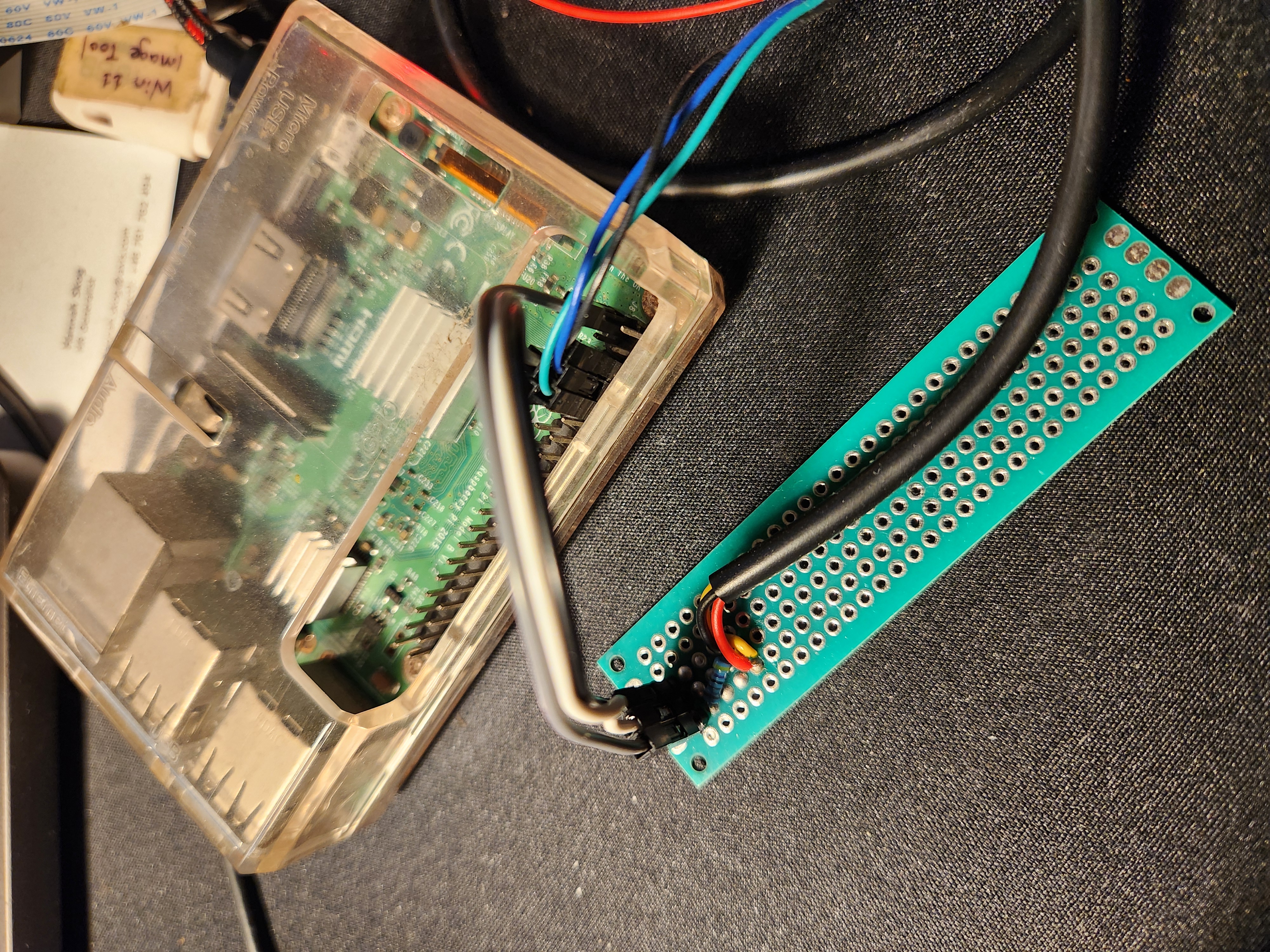
Wiring Diagram
Connect the DS18B20 to your Raspberry Pi as follows:
| DS18B20 Pin | Wire Color (typical) | Raspberry Pi Pin |
|---|---|---|
| VCC | Red | 3.3V (Pin 1) |
| GND | Black | GND (Pin 6) |
| DQ (Data) | Yellow | GPIO4 (Pin 7) |
Important: Place a 4.7kΩ pull-up resistor between the DQ (Data) line and the VCC (3.3V) line. This resistor is essential for proper 1-Wire communication. GPIO4 is the default pin used for the 1-Wire communication.
Accessing via UART Console
I am currently accessing the Raspberry Pi using the UART console as it is often easier to catch early boot errors instead of waiting for SSH to become active. Also, SSH is not available by default in the Yocto image. If you want SSH access, you can enable it by modifying the kas configuration.
Building the Image
Step 1: Setting Up the Yocto Build Environment
In the previous post, we created an image for the RISC-V architecture. Similarly, try to create a kas configuration file for generating the image for our board.
I have updated the meta-advent layer to include the configuration for the Raspberry Pi. Just do a git pull!
kas build kas/build-rpi.yml
This command will build the core-image-minimal.
Step 2: Flashing the Image
Once the build completes, locate the output image:
ls build/tmp/deploy/images/<your-pi-model>/
The output is a .wic.bz2 file along with a .wic.bmap file, which can be flashed using bmaptool. Alternatively, extract the .bz2 image and flash it using the Raspberry Pi Imager.
Step 3: Verifying the 1-Wire Interface
Once booted, verify that the 1-Wire interface is active and the sensor is detected:
# Check if the w1 bus is available
ls /sys/bus/w1/devices/
You should see a directory starting with 28- followed by a unique identifier — this is your DS18B20 sensor. The 28 prefix indicates a DS18B20 family device.
You can navigate to the sensor’s directory and read the temperature:
cat /sys/bus/w1/devices/28-*/w1_slave
You’ll see output similar to:
70 01 55 05 7f a5 a5 66 c7 : crc=c7 YES
70 01 55 05 7f a5 a5 66 c7 t=23000
Understanding the Output
- First line: Raw data bytes followed by a CRC check result
crc=c7 YESindicates the data integrity check passed- If you see
NO, there’s a communication error
- Second line: Contains the temperature value
t=23000means 23.000°C (the value is in millidegrees Celsius)- Divide by 1000 to get the temperature in °C
Expected Outcome
After completing this tutorial, you should have:
- A Raspberry Pi running a custom Yocto-built Linux image
- A DS18B20 temperature sensor properly wired and detected
- The ability to read real temperature data via the sysfs interface
- Understanding of the 1-Wire protocol and its Linux implementation
When reading from the sensor, you should see output like:
70 01 55 05 7f a5 a5 66 c7 : crc=c7 YES
70 01 55 05 7f a5 a5 66 c7 t=23000
This indicates:
- The sensor is properly connected
- CRC validation passed (data is valid)
- Current temperature is 23.0°C
Troubleshooting
Sensor not detected (no 28-* directory):
- Verify wiring connections, especially the pull-up resistor
- Check that the 1-Wire overlay is enabled in the device tree
- Ensure GPIO4 is being used for the data line
Build fails:
- Ensure all dependencies are installed on your host
- Review kas and bitbake logs for specific errors
Image doesn’t boot:
- Verify the SD card was flashed correctly
- Check serial console output for boot messages
- Ensure the correct machine configuration is used
What’s Next?
Now that we have real hardware working with a custom Linux image, future posts will explore:
- Building user-space applications to interact with sensor data
- Data logging
- OTA updates
Extras
- Adafruit DS18B20 Tutorial: https://learn.adafruit.com/adafruits-raspberry-pi-lesson-11-ds18b20-temperature-sensing - Comprehensive guide with wiring diagrams
- DS18B20 Datasheet: https://www.analog.com/media/en/technical-documentation/data-sheets/DS18B20.pdf - Official datasheet with timing and electrical specifications
- kas Documentation: https://kas.readthedocs.io/ - Official kas documentation
- meta-raspberrypi Layer: https://github.com/agherzan/meta-raspberrypi - Yocto layer for Raspberry Pi support
- Linux 1-Wire Documentation: https://docs.kernel.org/w1/index.html - Kernel documentation for the 1-Wire subsystem